

How To Create A Battery Charger
There are several types of batteries you may encounter out there. Each of them has different internal chemistry and has quite different charging requirements. So in this tutorial, we will take a closer look at the charger for each type (chargers only and not the battery types' internal chemistry) and introduce you to battery charger circuits.

From a safety point of view, be careful not to overcharge or reverse-charge batteries as they can become hot and even catch fire or explode. (This is not an idle threat – it happens!)
But before we dive deeply into that, let's recall two things: (1) constant voltage, where the supply voltage is fixed, and the battery decides on how much current to draw (if the battery is very flat and wants to demand a huge current, the supply will limit this); and (2) constant current, where the charger keeps a constant current through the battery even as the battery cell voltages rise by controlling the voltage across them.
Now, let's get to the battery chargers.
Sealed Lead Acid
Sealed Lead Acid or SLA is great when you have space, and one of their best characteristics is the ability to maintain a charge on the shelf for a long time. SLAs are generally charged from a constant voltage source. This means that the charger is set at a specific voltage that remains unchanged through the cycle, allowing the battery to initially demand a high current which then tapers off as it charges. The initial current has to be limited to prevent damage and overheating.
An SLA side usually lists a range of voltages for a trickle charge where the battery will be permanently on charges, such as in a UPS and a cyclic range where the battery gets removed, used, and then put back on charge.
In the image below, the initial charge (limit to this) is shown. In a simple charger, the cyclic rate has to be monitored as at this rate; the SLA will overcharge once it has reached capacity. Charging can be done with a current limiting bench PSU. Just set the voltage to the rate you will use and set the current limit to the value specified on the battery.
Shown below are an SLA charger that automatically switches rate when the battery is fully charged and the side view of an SLA battery with the charging rates, and a view inside the charger.
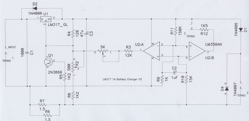
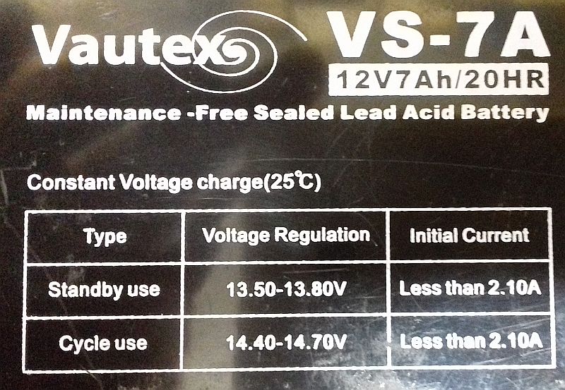 | 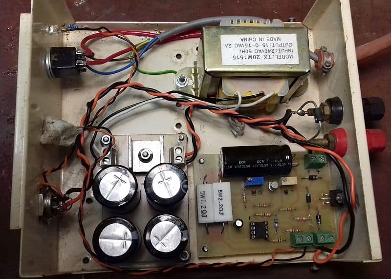 |
| Side view of a SLA battery | Inside an automatic charger |
Nickle Cadmium (NiCd) and Nickle Metal Hydride (NiMH)
I have bundled these together as they have some similar charging requirements.
Nicads were very popular in the last two decades but are gradually replaced with Nickle Metal Hydride (NiMH) due to their memory effects. They have a slight tendency to memory but not as severe.
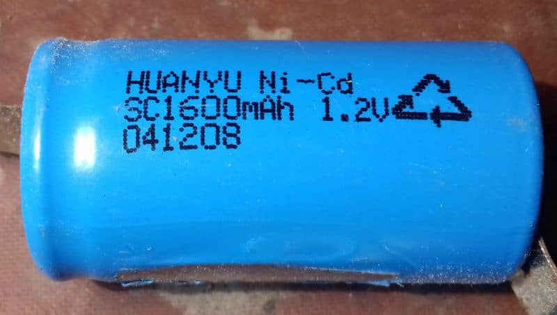
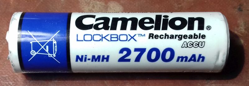
Both types offer convenience and the ability to charge as many as you like in series. Both can be charged with a constant current, and if you stay below C/10, you can charge them indefinitely. (C is the battery capacity marked on the side, e.g., 2700mAH, so C/10 is 270mA).
Shown below are two options. On the left is a discrete transistor charger (this is a good choice as you can easily scale it up to higher voltages and currents with suitable components). On the right is the same thing using an LM317 adjustable regulator configured as a constant current source. In both examples, I have designed them for a 12V battery pack and a charge rate of 50mA.
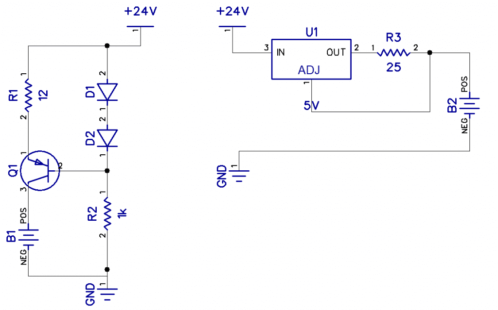
D1, D2, and R2 provide a constant volt drop at the base of 1.2V, as the base-emitter voltage will always force 0.6V. This means R1 will always have 1.2-0.6, i.e., 0.6 across it, and so by choosing R1 correctly, we have a programmable constant current source. In this case, R=V/I i.e., 0.6/50mA =12Ω.
In the LM317 version, the IC forces a 1.25V reference voltage between Vadj and Vout, so choosing R3 for 1.25V at 50mA, R=V/I = 1.25/50mA = 25Ω. While charging, cells have a voltage of up to 1.7V across each other. Thus, for a 12V pack, that's 20V. That's why I choose the higher 24V supply.
 |  |
Lithium Polymer
LiPo batteries are becoming popular in RC models, laptops, and power banks as they have a conveniently higher terminal voltage (3.7V) and a huge capacity for their size. The downside is that they require careful and controlled charging. A TP4056 chip can easily do it and even better with a TP4065 module. This can be driven from a PSU of 4 to 8 V or 5V in a USB port. When the battery reaches 4.8V, it is fully charged, the module will detect this for you and light up its green LED.
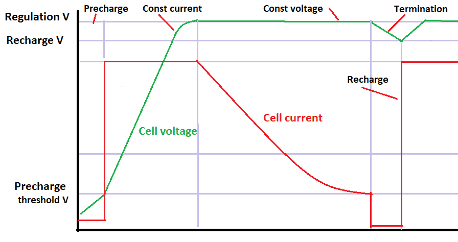
The 4056 ES IC on the Li-Po charger chipsets the four sequential charging stages of the battery. After a fully discharged Li-Po battery is connected to the module, it first does a precharge stage. During this stage, the current is set to 10% of its maximum charging current. Next, a constant current charging stage follows where the voltage increases steeply until it levels off into a constant voltage stage. Finally, the current starts to tail off, and when it becomes 10% of its maximum charging current, it reaches the termination of the stage, and the red LED goes off, and the green one comes on.
Shown below is the TP4056 I have:
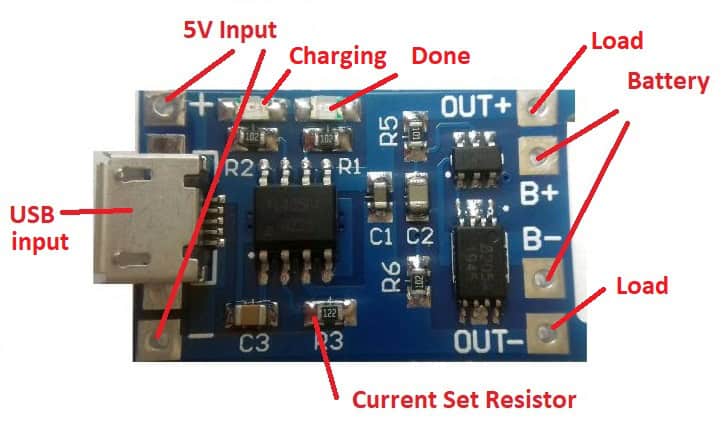
There are many different versions of the module, and yours will probably look a bit different. Here is a resource for the module I have.
This module also has OUT pins to connect your circuit, and the module will monitor and prevent over-discharge as well.
Connect the 5V pins or the USB connector (caution: the default charge rate is 1A, and some USB ports cannot supply this) and the battery to the battery terminals. Remember you should not put LiPo cells in series. It would help if you had a separate TP4056 module for each one.
Here's how to change the charging current: Look for and locate your version of the R3 mark. In some other types, this is R4, and it will be a 1k2 SMD resistor and will say 122 on top. Carefully remove this and solder 2 wires. Now add a resistor across these according to the table to set your own charge rate.
| Resistor | Charging current |
| 6.2k | 200mA |
| 5k | 250mA |
| 4k | 300mA |
| 3k | 400mA |
| 2k | 580mA |
| 1.5k | 780mA |
| 1.2k | 1000mA |
Although making a charger is not too complicated, always remember that utmost care is necessary to protect the battery.

How To Create A Battery Charger
Source: https://www.circuitbasics.com/battery-chargers/
Posted by: adamsfirwass66.blogspot.com
0 Response to "How To Create A Battery Charger"
Post a Comment